Brief Introduction
Bentonite Geosynthetic clay liners (GCL) consist of bentonite, woven between two geotextile layers. This lining mechanism uses the properties of bentonite and the material to which it is bonded holds the clay in place.
GCLs require soil cover of at least 300mm to provide sufficient normal force to confine the expansion of the bentonite core layer. The bentonite swells and extrudes through the geotextile fabric at the overlap, forming a seal by producing a dense and uniform clay barrier with the same hydraulic qualities in all parts of the clay liner.
Experience
GCLs are used in a range of environmental and containment applications, particularly when performance is critical and when penetration risks are present. Examples include landfill cappings and cutoff walls to contain pollution.
Our GCLs was installed 130000 square meters in Guangdong Chaozhou Landfill Project.
Site preparation
Subgrade preparation required removal of silt and over-excavation of 400mm to allow for covering of the GCL. Batters were trimmed to 1:3. Spoil was placed adjacent to the channel to facilitate backfilling. Loose rubble was removed before rolling of subgrade.
Installation
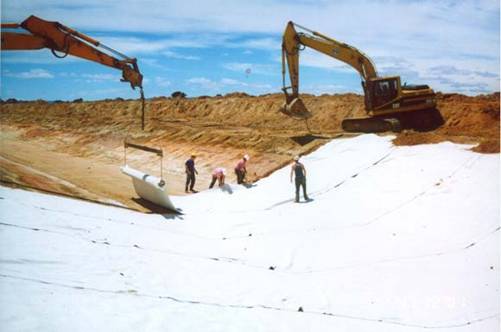
A lifting frame fitted to an excavator suspended the GCL roll and facilitated placement across the channel. The material was pulled across the channel by a crew of four and up the channel bank as far as possible. It was then attached to another lifting frame (constructed for the project with grip plates attached) and a second excavator. The second excavator then assisted the crew to drag the material up the bank to the required height. Each length of liner was overlapped by 300mm , with the top of the overlap on the downstream side. It took two days to install the liner, and an additional three days to repair areas ripped by equipment moving over the liner.

Figure 1 Installing the GCL.
The GCL was anchored by placing a minimum of 400mm of backfill over the material on a berm located 300mm above the high-water mark.
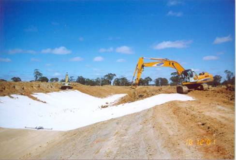
Excavators then covered the liner with 400mm of backfill material. The recommended minimum backfill is 300mm , but this thickness is difficult to place and compact. Once the cover had been placed an excavator compacted the backfill using its tracks but had to move cautiously to avoid movement and damage to the GCL. On the sides a 3:1 bank slope was sufficient to maintain the backfill material on the liner without it slumping.

Figure 2 Burying the GCL.
The end of the GCL was keyed into the channel profile to a depth of 400mm in a 1.2m wide trench across the channel. Backfill material was then compacted in the trench.
The site was fenced to prevent access to sheep and cattle, and signs identifying the liner's location were installed.
Specialised equipment
Lifting frames were required to hold the GCL roll and to pull the material to other side of the channel.
Installation issues
The material was heavy, an difficult and labour intensive to handle. Its white colour produced significant sun glare.
The material tore easily when the compaction equipment turned. Compaction therefore focused in two separate directions - up and down the bank and backwards and forwards along the channel length - to avoid the need for turning. Four passes were found to provide a reasonable compaction to ensure longevity of the cover. The supplier recommended a loose covering.
The subgrade appeared to settle after the backfill material was placed and caused the joins to come apart. These had to be excavated and additional GCL laid. Wet soil patches also appear to have caused differential settlement during compaction.
The joining overlap of 300mm appeared to be insufficient.
Weather considerations
Installation in wet conditions is not possible as rain is absorbed by the bentonite, making the liner heavier and harder to handle.
Durability
The lifespan of covered GCL is estimated to be 25 years.
Advantages and disadvantages
Advantages
It was possible to order the exact length of liner required across the channel to be supplied on one roll. This eliminated the need to ®cut and paste' the liner.
The material is suitable for sites where no clay source was available.
Disadvantages
The material is very heavy, difficult to handle, and labour intensive to install.
Main Applications of GCLs
1. being used under the geomembrane of main liners of landfill;
2. being used under the geomembrane of secondary liners of landfill;
3. being used between geomembrane(up) and clay layers(downside of landfill), i.e. to form a three layers liner together in the landfill;
4. being used under the geomembrane of top covers of landfill;
5. acting as abutting joint with the geomembrane used in the vertical cutoff wall;
6. Being used above the the geomembrane in order to prevent the piercing of coarse grains to the geomembrane;
7. being used as the second liner of underground water well s .
Products specifications:
Width: |
5.8m ( best suit for 20' ctner loading) |
Length: |
30meters |
Permeability Coefficient: |
1.25-3.54 Á10 -9cm /sCBR |
Bursting Strength |
1.2KN |
Puncture Resistance: |
0.34KN |
Technical Data |
Items |
Testing Method |
Required values |
Bentonite Swell Coefficient |
ASTM D 5890 |
Ý 24mL/ 2g |
Fluid Loss |
ASTM D 5891 |
Ü 18mL |
Bentonite Weight per unit |
ASTM D 5993 |
Ý 4.8kg /m 2 |
Tensile Strength |
ASTM D 4632 |
Ý 400N |
Peeling Strength |
ASTM D 4632 |
Ý 65N |
Indicating Flowmeter |
ASTM D 5887 |
Ü 1 Á 10 -8 m 3 /m 2 /sec |
Permeability Coefficient |
ASTM D 5887 |
Ü 5 Á 10 -9 cm /sec |
Tensile Strength after soaking |
ASTM D 5321 |
Ý 24kPa typical |
|
NATIONAL INSPECTION REPORT
BY INSPECTION CENTER OF WATER RESERVANCY BUREAU OF CHINA
REPORT DATE: APRIL 5,2006
ITEMS |
UNIT |
AVERAGE VALUES |
SAMPLE NUMBERS |
TOLERANCE |
TESTED SAMPLE |
Bentonite Geosynthetic clay liners (GCL) consist of bentonite, woven between ONE WOVEN T AND ONE NONWOVEN geotextile layers |
SWELL INDEX |
Ml/ 2g |
24.9 |
5 |
0.034 |
Bentonite Mass |
g/m2 |
5583 |
10 |
/ |
thickness |
mm |
8.02 |
10 |
0.024 |
Strenth at yeild |
Kn/m |
11.6 |
6 |
0.023 |
Enlongation at yield MD TD |
% |
10.5 |
6 |
0.067 |
% |
6.1 |
6 |
0.121 |
Puncture Resistance |
N |
405 |
6 |
0.031 |
Peeling Strength |
N/ 10cm |
65.8 |
6 |
0.043 |
Permeability |
M/s |
2.94x10 -11 |
3 |
/ |
|


